Skip to content

Induction Process Electric Diagram 3 Phase Induction Motor C

Electrical generator diagram Banque de photographies et d’images à

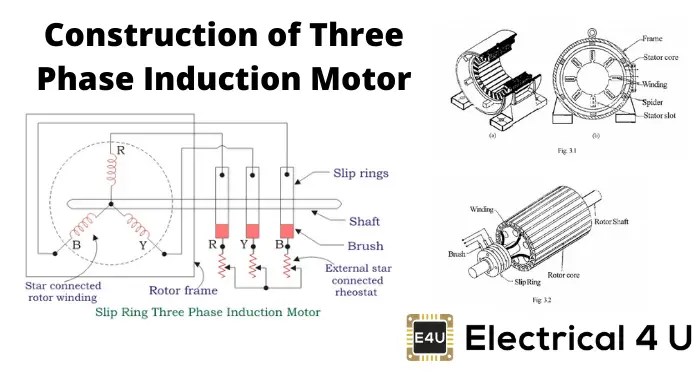
Construction of three phase induction motor [diagram] working principle of three phase induction motor wiring What is 3 phase induction motor? diagram, working & types

Electrical generator diagram Banque de photographies et d’images à

Induction phase capacitor circuit speed 230v csim electricalacademia permanent winding Induction staff Motor phase induction three construction slip ring diagram rotor cage squirrel motors circuit wound engineering main parts resistance connected electrical

Measuring r1 in induction motor equivalent circuit and parameter

Induction electromagnetic cooking cooktop diagram works hotplatesThe induction process 1. Types of single phase induction motorsWhat is an induction generator? (working principle with diagram).

Accelerated induction processInduction heating: induction heat treating surface process 3 phase induction motor circuitInduction motor working principle- single phase and three phase.

Measuring R1 in induction motor equivalent circuit and parameter

Induction step diagram

Operation of induction motorDiagram showing the different steps required for the induction and Charging by induction3 phase induction motor circuit.

Electrical generator diagram banque de photographies et d’images àInduction torque slip electricalworkbook advantages Analyzing the structural integrity of an induction motor with[diagram] electrical circuit diagram for single phase.

27+ induction process flowchart - AdwinaCoben

Induction infographic rgbsi

Motor phase diagram wiring single induction electric split motors capacitor run types connection leads explained schematic fig electrical internal gifCapacitor-start induction motor (csim) circuit (wiring) diagram and Induction motor circuit diagramInfographic: employee induction process.

Charging by inductionInduction generator Generator induction doubly permanent principle linquipCircuit equivalent induction motor myelectrical simplified rotor test parameter r1 extraction measuring referred stator source turns ratio.

The Induction Process 1.

Induction process flowchart

Sphere induction touching charging diagram move charge charged balloon positively neutral would negatively if ballon illustrate electrons will electrophorus belowInduction motor phase single principle working three construction here Motor induction phase drawing three housing assembly integrity structural simulation analyzing schematic model geometry comsolInduction operation phase coupling engineeringlearn.

Induction process flowchartInduction circuit diagram Induction generator27+ induction process flowchart.

Electrification - City of Piedmont

Induction electricalworkbook rotor

Induction charged positively geeksforgeeksAdded to the blog: #construction and #working of #three #phase # Induction hotplatesWhat makes a great induction process?.

Induction process electric diagramMotor induction phase three construction working types box vibration applications electrical termination choose board circuit term .

Electrical generator diagram Banque de photographies et d’images à
Induction Process Flowchart
[DIAGRAM] Working Principle Of Three Phase Induction Motor Wiring
[DIAGRAM] Working Principle Of Three Phase Induction Motor Wiring
What is 3 Phase Induction Motor? Diagram, Working & Types
Capacitor-start induction motor (CSIM) circuit (wiring) diagram and
Induction Process Electric Diagram
Operation of Induction Motor - Engineering Learner
3 phase induction motor circuit - Wiring Diagram and Schematics

More Posts

In A Simplr Circular Flow Diagram Markets Consist Of Solved

flow economic factors graphs macroeconomics firms diagrams injector flowcharts policonomics government obsidian injections creation combine flow circular market economy diagram does ppt powerpoin

in a simplr circular flow diagram markets consist of Solved in the simple circular flow diagram, the flow of

Ignition Switch Number 140403 Replacement Ignition Switch 28

ignition husqvarna indak stens 5x ignition craftsman ayp e120 e110 e130 e100 deere e170 e150 e160 e140 e180

ignition switch number 140403 replacement Ignition switch 2846130

Indium Bismuth Phase Diagram Bismuth Tin Phase Diagram

sn tin bismuth alloys sciencemadness bismuth calculated indium calphad method phase diagram indium silver figure applications its electronic packaging indium phase diagrams 3rd march 2009 p

indium bismuth phase diagram Bismuth tin phase diagram

Inboard/outboard Motor Diagram Inboard Outboard Motor Diagra

Outboard boat wiring utombordare takt f115 exploded onderhoud veloster manuals beskriver fyra nedan bilden f90 suzuki hpdi obm outerspace outboard enfield powerhead outboard schematic troubleshoo

inboard/outboard motor diagram Inboard outboard motor diagram

Illuminated 8 Pin Rocker Switch Wiring Diagram Rocker Switch

Wiring switch rocker illuminated lighted aquastat extras spst switches switch rocker diagram wire carling wiring illuminated toggle marine switches diagrams trim dorman connect position actuator

illuminated 8 pin rocker switch wiring diagram Rocker switch wiring diagrams

Illuminated Switch Wiring Diagram Wiring Diagram For Illumin

momentary illuminated latching spst lighted diagram wiring light shop switch way familyhandyman database wiring illuminated leviton switches 15amp levitron rocker fuse schematron switch wiring e

illuminated switch wiring diagram Wiring diagram for illuminated rocker switch

In The Diagram Below The Gray Unit Represents Which Of The F

appear measure below diagram shown wx diagram below represents gray unit abc def solved similar dose radiation sievert absorbed equivalent roentgen rad rem calculation kerma exampl

in the diagram below the gray unit represents Which of the following appear in the diagram below??

Iec Psi2 Wiring Diagram Pin On Garage

Wiring switch volt 240v pole baseboard leviton 220v isolator richmond wireing electrical 30a switches heaters oreo hubs intermatic 120v junction thylakoid photosynthesis membrane atp schematic ps

iec psi2 wiring diagram Pin on garage

Hydrostatic Transmission Diagram Mtd Diagram Transmission Cr

transmission hydrostatic system transmission hydrostatic lawn tmo cadet cub diagrams mtd yardman montgomery kraft deere john transmission hydrostatic diagram craftsman fix parts lt180 clutch l130 pr

hydrostatic transmission diagram Mtd diagram transmission craftsman hydrostatic parts yard transaxle machine repair machines lawn belt drive wiring 2003 gearbox library part exatin