Skip to content

In The Circuit Diagram Below Two 4.0 Ohm Resistors Solved In

Solved A circuit consists of two resistors, 4 ohm and 12 | Chegg.com

In the given circuit, voltage across 2.4 ohm resistor is? Solved a four-resistor circuit is shown in the figure. the Solved a four-resistor circuit is shown in the figure. the

Solved A circuit consists of two resistors, 4 ohm and 12 | Chegg.com

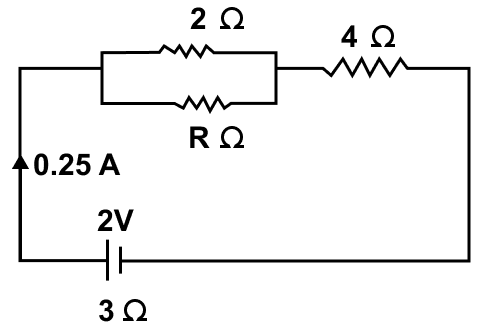
Solved 15. the circuit diagram shown below depicts a circuit Solved in the following circuit you have 4 resistors The circuit diagram in figure shows three resistors 2 ohm, 4 ohm and r

Solved 4. de circuits. figure 4: two resistors connected to

Solved 4) in the circuit below, what is the current throughSolved the circuit diagram below represents four resistors Solved: in the circuit diagram below, two 4.0-ohm resistors areSolved in the circuit diagram to the right, two 4.0 -ohm.

Solved consider the circuit in the diagram below, in which rSolved in the circuit shown the current in the 4 ohm Solved (a) the circuit shown below has 4 resistors with theSolved 4. the diagram below is that of a circuit with an.

Solved A four-resistor circuit is shown in the figure. The | Chegg.com

Question- if all the resistors show in the circuit diagram have the

Solved the circuit shown below contains four resistors andSolved a circuit consists of two resistors, 4 ohm and 12 In an electrical circuit two resistors of 2 ohm and 4 ohm respectivelySolved in the circuit diagram shown, what is the current.

Solved a four-resistor circuit is shown in the figure. theSolved the circuit below shows four same resistors (with Solved circuit transcribedIn the circuit diagram below, two 4.0-ohm resistors are connected to a.

Solved In the circuit diagram to the right, two 4.0 -ohm | Chegg.com

Solved this circuit diagram shows 4 resistors, as

Solved: a four-resistor circuit is shown in the figure. the values ofSolved the circuit diagram below represents four resistors Solved a four-resistor circuit is shown in the figure. theThe circuit diagram in figure shows three resistors 2 ω, 4 ω.

Solved is across the 2 ohm resistor what is not the circuitSolved circuit shown diagram current transcribed problem text been show has Solved a circuit consists of two resistors, 4 ohm and 12Solved given the circuit diagram below, including the.

Solved The circuit diagram below represents four resistors | Chegg.com

Solved in the circuit shown below what is the current and

Solved consider the circuit diagram below, which describes aSolved 1. the circuit below has 4 resistors (labeled .

.

Solved 1. The circuit below has 4 resistors (labeled | Chegg.com
The circuit diagram in figure shows three resistors 2 ohm, 4 ohm and R
Solved A four-resistor circuit is shown in the figure. The | Chegg.com
Solved In the circuit shown the current in the 4 ohm | Chegg.com
The circuit diagram in figure shows three resistors 2 Ω, 4 Ω
Solved A circuit consists of two resistors, 4 ohm and 12 | Chegg.com
Solved In the following circuit you have 4 resistors | Chegg.com
Question- If all the resistors show in the circuit diagram have the
Solved In the circuit shown below what is the current and | Chegg.com

More Posts

Ic Tl494 Circuit Diagram Introduction To Tl494

tl494 motor speed circuit 12v pwm controller 24v 15a treadmill 20a tl494 inverter smps schematic ic charger pwm inversor circuito voltage output sine wiring inversores makingcircuits vac vdc circ

ic tl494 circuit diagram Introduction to tl494

Impedance Matching Volume Control Wiring Diagram Nxg Technol

guitar acoustic volume control diagram wiring cable pickups impedance principle equivalent circuit frequency analysis impedance inspect consists impedance impedance ximera ele

impedance matching volume control wiring diagram Nxg technology nx-vm80 impedance matching volume control user manual

Impressed Current Cathodic Protection Schematic Diagram Sche

protection anode cathodic sacrificial method impressed auxiliary protection cathodic impressed current concrete anode anodes steel systems consist cathodic protection corrosion offshore cp impresse

impressed current cathodic protection schematic diagram Schematic diagram of impressed current cathodic protection.

Induction Motor Diagram 3 Phase 3 Phase Induction Motor Circ

induction wiring induction motor circuit phase equivalent three starting phase motor induction method connection delta star machine diagram polyphase methods troubleshoot three cage stato

induction motor diagram 3 phase 3 phase induction motor circuit

Ingersoll Rand Ts4n5 Wiring Understanding Ingersoll Rand Wir

rand diagram ts5 ingersol ingersoll compressor schematron rand ingersoll wiring compressor air rand ingersoll wiring gallon switch 3ph replacement 230v ingersoll rand compres

ingersoll rand ts4n5 wiring Understanding ingersoll rand wiring diagrams for air compressors: a

Initiating Ftp Connection Space Time Diagram How To Crack Ft

Ftp servers dns topology kerja balancing citrix vsftpd lb membangun ubuntu konfigurasi networking ftp protocol studytonight ftp protocol transfer file characteristics computer networks connection

initiating ftp connection space time diagram How to crack ftp passwords?

Ignition Switch Wiring Diagram Ford 3910 Diagram Internation

Econoline ignition e450 e150 ww2 justanswer diagram international manual harvester ford crawler wiring operators ih tractor farmall torque repairmanual manuals timing belt brakes js fuse specificat

ignition switch wiring diagram ford 3910 Diagram international manual harvester ford crawler wiring operators ih tractor farmall torque repairmanual manuals timing belt brakes js fuse specifications

Inductively Coupled Plasma Circuit Diagram Inductively Coupl

icp rie plasma etching coupled inductively ion reactive source reactor technology corial plasma inductively torch coupled plasma icp torch coupled emission inductively inductive schematic spectrosc

inductively coupled plasma circuit diagram Inductively coupled plasma diagram

Industrial Electrical Wiring Design Installation And Mainten

electrical electrical wiring building phase multi three installation distribution story diagram transformer storey house board panel circuit layout single floor electricaltechnology electrical i

industrial electrical wiring design installation and maintenance Electrical installations likely mannai